Dwyer LTC User Manual

Browse online or download User Manual for Routers Dwyer LTC. Dwyer LTC User Manual

  • Download
  • Add to my manuals
  • Print
  • Page
    / 2
  • Table of contents
  • BOOKMARKS
  • Rated. / 5. Based on customer reviews
Page view 0
The Series LTC Tilt Switch Control Units feature an adjustable time
delay and a logic selector switch. There are two contacts for connection
to the probe (three contacts for intrinsically safe probes); three for the
input power; and two sets of output contacts, each with one normally
open, one normally closed, and one common. Signal lights, relay, and
transformer are all accessible with the box cover open allowing for easy
maintenance. The controller output is through a relay, which provides a
change in contacts as the probe moves from vertical to tilt and vice
versa. The user may choose to employ either the normally open, nor-
mally closed, or both sets of contacts to perform switching operations in
the system. In addition, an adjustable time-delay feature may be
assigned to either the vertical or the tilt position to prevent false signals.
The time delay is adjustable from one to ten (1 to 10) seconds. The relay
assumes the de-energized position upon reaching the end of the delay
period-as well as upon failure of power to the controller.
Series LTC Tilt Switch Control Unit
Specifications - Installation and Operating Instructions
Bulletin L-29
SPEC
IF
IC
A
T
ION
S
T
e
mp
e
ra
t
u
re
L
imit
:
1
2
5
°F
m
a
x
(
5
2
°C
)
.
Po
we
r
R
e
q
u
ire
me
n
t
:
1
1
5
VAC
@
5
0
/6
0
H
z.
Po
we
r
C
o
n
s
u
mp
t
io
n
:
1
0
W
.
Swit
c
h
T
y
p
e
:
D
PD
T.
Ele
c
t
ric
a
l
R
a
t
in
g
:
1
0
A
@
1
1
5
VAC
.
En
c
lo
s
u
re
: N
o
n
e
o
r
C
a
r
b
o
n
Ste
e
l
h
o
u
sin
g
w
ith
p
o
lye
ste
r
co
a
tin
g
.
En
c
lo
s
u
re
R
a
t
in
g
:
N
o
n
e
o
r
N
EM
A
4
.
Ele
c
t
ric
a
l
C
o
n
n
e
c
t
io
n
s
:
Scr
e
w
Te
r
m
in
a
l.
C
o
n
d
u
it
C
o
n
n
e
c
t
io
n
s
:
N
o
n
e
.
In
d
ic
a
t
io
n
L
ig
h
t
:
Gr
e
e
n
(
w
h
e
n
r
e
la
y
is
e
n
e
r
g
ize
d
a
n
d
p
r
o
b
e
ve
r
tica
l)
,
R
e
d
(
w
h
e
n
r
e
la
y
is
d
e
-
e
n
e
r
g
ize
d
a
n
d
p
r
o
b
e
tilte
d
)
.
In
d
ic
a
t
io
n
L
ig
h
t
Po
we
r
R
e
q
u
ire
d
:
1
8
VD
C
.
Time
D
e
la
y
:
1
to
1
0
se
c. Ad
ju
stm
e
n
t
w
ill
d
e
la
y
o
u
tp
u
t
r
e
la
y
a
ctio
n
.
IN
D
IC
A
TOR
L
IGH
T
S
N
o
r
m
a
l
(
g
r
e
e
n
)
:
L
ig
h
t
o
n
w
h
e
n
r
e
la
y
is
e
n
e
r
g
ize
d
;
p
r
o
b
e
is
ve
r
tica
l.
Ala
r
m
(
r
e
d
)
:
L
ig
h
t
o
n
w
h
e
n
r
e
la
y
is
d
e
-
e
n
e
r
g
ize
d
;
p
r
o
b
e
is
tilte
d
.
WIR
IN
G
All w
ir
in
g
sh
o
u
ld
b
e
in
co
m
p
lia
n
ce
w
ith
a
p
p
lica
b
le
L
o
ca
l, F
e
d
e
r
a
l, a
n
d
Sta
te
co
d
e
s.
C
a
b
le
is
co
n
n
e
cte
d
to
th
e
p
r
o
b
e
.
F
o
r
co
n
tr
o
l u
n
it L
T
C
2
, h
o
le
s m
u
st b
e
m
a
d
e
in
th
e
co
n
tr
o
l u
n
it to
co
n
n
e
ct
the probe wire to the
e
le
ctr
ica
l co
n
n
e
ctio
n
s in
sid
e
th
e
co
n
tr
o
l u
n
it.
Typically, these holes are made on the bottom surface of the unit.
PROXIMITY CONTROLS
Phone: 219/879-8000 www.dwyer-inst.com
A DIVISION OF DWYER INSTRUMENTS, INC.
Fax: 219/872-9057 e-mail: [email protected]
P.O. BOX 373 MICHIGAN CITY, INDIANA 46360, U.S.A.
8
-3/4
(
222.25)
8
-1/4
(
209.55)
1-9/32
(32.54)
4
(
101.6)
1
-21/32
(
42.06)
R
ED LENS
G
REEN LENS
9-1/2
(241.3)
4
4
-7/8
(
123.83)
3
-29/32
(99.16)
6
-3/64
(153.59)
CONTROL UNIT
Page view 0
1 2

Summary of Contents

Page 1 - PROXIMITY CONTROLS

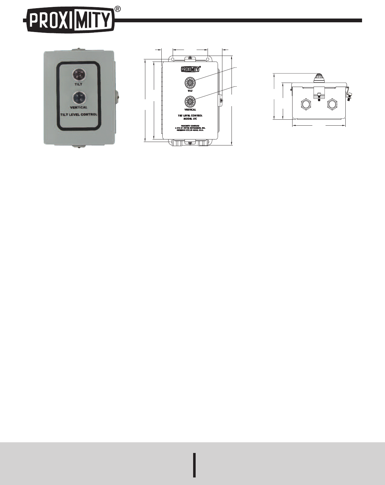
The Series LTC Tilt Switch Control Units feature an adjustable timedelay and a logic selector switch. There are two contacts for connectionto the pro

Page 2

INSTALLATION INSTRUCTIONSMOUNTINGThe control unit should be mounted in an area free from vibration and thetemperature should not exceed 125°F (52°C).

Comments to this Manuals

No comments